Floor Swirl Diffusers: Types and Applications
1. INTRODUCTION
Displacement air distribution has for many years been one of the preferred methods for cooling and providing fresh air to the occupants of sustainable buildings. This is because the principles of displacement air distribution – effectively enveloping occupants in a layer of fresh air – bring with them a host of energy efficiency and indoor climate advantages. However, traditional perforated displacement diffusers are often difficult to locate in typical commercial offices, as they are bulky and freestanding (in the form of cylindrical totems) or need to be integrated into walls, usually at a low level.
With the advent of raised floor systems in many commercial offices, it has become possible to provide displacement air via a less bulky alternative – floor diffusers fed from the plenum beneath the floor. Many floor diffusers have been developed for this purpose. Among these, the most successful in the office environment have been floor swirl diffusers (floor-type swirl diffusers). This article examines the pros and cons of four basic floor swirl diffuser technologies and suggests appropriate application areas for each.
2. DISPLACEMENT AIRFLOW
The principles of displacement airflow traditionally involve supplying air that is slightly cooler than the room temperature (max DT=4-5C) and has high indoor air quality. This supply air filters out from low-level, large-surface perforated diffusers, then gently fills the floor of the living space like a cool, fresh air lake. Heat sources are enveloped in coolness and freshness as the air rises in natural convection plumes, then accumulates in stratified layers of heat and pollutants at high levels and is removed from the environment. Building occupants are effectively protected in a microclimate of approximately 23°C, and the supply air temperature is typically only slightly lower, around 20°C. Despite this relatively high supply air temperature (compared to mixed-flow systems), the supply-return temperature difference exceeds -6K for standard commercial ceiling heights of 2.7m, and -12K in higher spaces. Consequently, the fan energy loss associated with higher supply air temperature is reasonable for standard office applications and actually results in savings in high ceilings. This is because the large void beneath high ceilings acts as a thermal reservoir, allowing the stratified layers floating above the occupied microclimate to trap even more heat, thereby increasing both the air temperature in the void and the supply-return air temperature difference.
From the above, the main advantages of displacement air distribution over mixed-flow systems can be defined as follows:
- Occupant indoor air quality (IAQ) is enhanced; ventilation effectiveness for seated occupants in typical commercial office applications can reach values of 2.0, far exceeding the typical 0.9–1.0 values for mixed-flow systems.
- Energy savings can be achieved by reducing outdoor air volumes without compromising indoor air quality.
- The low-temperature difference supply air allows chiller units to operate with increased coefficients of performance (COP).
- The elevated supply air temperature increases the potential for free cooling and associated energy savings.
However, the main disadvantages of traditional displacement ventilation provided via perforated wall-mounted or freestanding diffusers are:
- The temperature difference between the supplied air and return air is relatively low at standard ceiling heights. Therefore, higher air volumes are required for cooling the space, which means larger duct and fan sizes and higher fan energy consumption.
- Perforated displacement diffusers are bulky and typically about 10 times the surface area of similar mixed-flow diffusers.
- When cold and dense air filtering from displacement diffusers enters the space, it creates a waterfall effect, flowing downwards and accelerating to spread across the floor. Therefore, occupants must sit at least 1m away from the diffusers; otherwise, they are exposed to air velocities above approximately 0.18 m/s at ankle level, which causes drafts.
- Low supply air temperatures cannot be used even with high heat loads; because the air temperature at ankle level should not fall below 21°C to prevent the sensation of cold feet.
- Even with high heat loads, low supply air temperatures should not be used, as the air temperature at ankle level should not be reduced below 21°C.
- A vertical temperature gradient greater than 2K/m (e.g., a temperature higher than 21°C at ankle level / 23°C at head level) causes thermal discomfort and is the primary limiting factor for the capacity of displacement airflow to remove heat from the environment.
3. FLOOR SWIRL DIFFUSERS FOR COMMERCIAL OFFICES
With the advent of the computer age, the use of raised floors to meet the cabling requirements of computer rooms offered a way to combine cool airflow from below with natural convection to meet the high cooling needs of computers and remove heat from above.
As a result, many types of floor-mounted diffusers were developed over the years. Most of the earliest designs were simple grilles that created strong air movement and drafts. This was acceptable in computer rooms, but by the late 1970s, demand in Germany shifted towards using underfloor air distribution in offices as well.
This was to combine the draft-free comfort, enhanced indoor air quality, and energy efficiency advantages of traditional perforated displacement systems with underfloor ventilation. Additionally, increased flexibility and lower life cycle costs could be achieved through raised floor systems.
However, the violent/penetrating airflows produced by simple floor grilles created drafts and mobilized heat at high levels, mixing heat and pollutants back into the occupied space. This not only destroyed the high temperature difference between supply and return air required for maximum heat removal with minimum fan energy, but also the microclimate around the occupants, which provided superior indoor air quality. These systems were plagued with complaints about discomfort and drafts, and it was only with the correct engineering solutions for diffusers – using swirl technology to solve these problems – that underfloor airflow became truly viable for offices.
3.1 Horizontal Throw Floor Swirl Diffusers
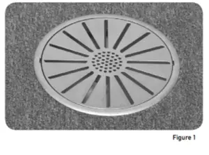
Over the years, many different displacement floor diffuser designs have been introduced. Among these, the most popular are typically models with a 200mm diameter surface that discharge air with a gentle, horizontal swirl pattern up to 30 L/s (Figure 1). The swirl throw ensures a rapid reduction in outlet velocity to minimize the risk of drafts for nearby occupants. The gentle and horizontal discharge ensures minimal mixing of the supplied air with heat and pollutants at the upper level, maximizing indoor air quality and typically providing ventilation effectiveness of 1.3 to 2.0 for seated occupants.
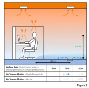
While indoor air quality is maximized, horizontal throw floor swirl diffusers are affected by the following limitations (Figure 2):
- Due to the risk of drafts at ankle level caused by the radial spread of horizontally discharged supply air, it is recommended to maintain a minimum distance of 1m between the diffuser and the nearest seating position. Ensuring this minimum distance is often difficult, especially in enclosed or multi-purpose spaces such as workstations, meeting rooms, or task group areas.
- The low air movement at head level resulting from the air pattern being gently directed towards the floor is not suitable for all users' comfort preferences. This is because many people prefer noticeable, or even increased, air movement and complain of stuffiness when this is not present. This is particularly true for tropical regions and the Asia-Pacific region in general.
- The cool supply air lake filling the floor causes the air temperature at ankle level (0.1m height) to be lower than the air temperature at head level (1.1m height) for seated occupants. For a standard 2.7m ceiling height, these systems are typically limited to a maximum specific sensible heat load of approximately 50 W/m² to prevent the vertical temperature gradient from exceeding 2K/m and thus the sensation of “cold feet, warm head”.
Horizontal throw floor swirl diffusers maximize indoor air quality and are highly suitable for applications with low equipment heat loads or high ceilings, or in core zones with low occupant density. However, when combined with the high equipment heat loads and increased occupant densities typical in most offices, and ceiling heights generally not exceeding 2.7m, this severely limits the applications where these diffusers can be used.
Nevertheless, these horizontal throw diffusers perform better than their upward throw counterparts in situations where low heat loads are present, such as libraries, and where diffusers need to be widely spaced. This is because horizontal throw floor swirl diffusers fill the floor with cool air, which then travels significant distances towards heat sources drawn upwards by natural convection.
3.2 Vertical Throw Floor Swirl Diffusers
Approximately 30 years ago, the vertical throw floor swirl diffuser was invented for the underwriters' area of the iconic Lloyds building at 1 Lime St in the City of London. This was to eliminate the excessively high heat loads in the space without exposing occupants to an excessive vertical temperature gradient and to provide enhanced indoor air quality (typically, the vertical throw floor swirl diffuser provides a ventilation effectiveness of 1.3 to 2.0 for seated occupants).
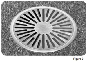
Floor swirl diffusers with a 200mm diameter surface (Figure 3) are designed to provide a highly inductive vertical throw. This creates mixing up to the head height of seated occupants, while preserving the stratified layers of heat and pollutants above this level. This is because vertical throw floor swirl diffusers ensure a rapid decrease in discharge velocity and quick temperature equalization of the supply air with the ambient microclimate air.
Compared to horizontal throw swirl diffusers, both much higher air volumes (up to 50 L/s) and much larger supply-return temperature differences (up to –10 K for a 2.7m ceiling height) are achieved. This makes it possible to remove heat loads of up to 200 W/m² in offices with heights of 2.7–3.0m.
In other words, in typical office environments, vertical throw floor swirl diffusers can provide three to five times more maximum sensible cooling capacity than similar horizontal throw systems (i.e., floor swirl or perforated wall-mounted), without exposing occupants to drafts or excessive vertical temperature gradients.
The great success of the vertical throw floor swirl diffuser in these and similar applications marked the beginning of a new era in displacement air distribution in offices.
The demand for personalized comfort led to the addition of the ability to adjust the airflow rate for the user. The requirement for individual diffuser control, referred to as task/ambient conditioning (TAC), increased following the work of leading researchers such as Bauman, who strongly advocated for these systems.
This emerged particularly after research by the Building Owners and Managers Association (BOMA), which surveyed 1829 office tenants in the US and Canada.
Based on this survey, Bauman concluded: “The only issue that appeared on both the list of most important features (96%) and the list of features tenants were least satisfied with (65%) is the ability of tenants to control temperature.”
Bauman also cited de Dear's [9] finding that building occupants without individual control capabilities were twice as sensitive to temperature changes as those with individual thermal control.
Webster states that user-controlled underfloor air distribution systems “increase employee satisfaction and productivity by giving employees more control over their local environments and improving the quality of indoor environments.”
However, Webster demonstrates that if the airflow rate in vertical throw floor swirl diffusers drops too low, an excessive vertical temperature gradient (i.e., “cold feet, warm head” discomfort) occurs. This is because the mixing height of the swirl flow falls significantly below the head level of seated occupants, thereby exposing the face area to the higher temperatures of the stratified zone. This situation can arise from user control of the diffusers if occupants significantly throttle the dampers of vertical throw floor swirl diffusers.
Today's vertical throw floor swirl diffusers are manufactured by various manufacturers to provide high-induction airflow in a vertical direction and typically allow personal adjustment of the airflow rate by the user through manual rotation of the diffuser face (clockwise to throttle the damper; counter-clockwise to open); thereby meeting the requirements for user-adjustable credits under Green Star.
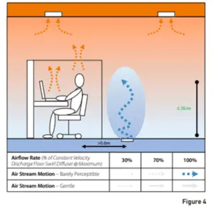
However, there are the following limitations for these diffusers (Figure 4):
- A minimum distance of 0.6m between the diffuser and the nearest seating area is generally recommended to prevent the radially spreading and vertically discharged airflow from colliding with seated individuals. This minimum distance is often difficult to maintain, especially in high-density offices or “plug-and-play” flexible workspaces.
- The barely perceptible air movement created by high-induction vertical throw is not suitable for all users' comfort preferences; many people prefer more noticeable or partially increased local air movement.
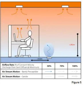
- To be effective, a wide range of airflow rate adjustment is required for the user to personalize their local climate solely through airflow rate adjustment. However, this brings the following problems (Figure 5):
- Significantly throttling the diffuser's airflow rate can lead to more air being discharged from other diffusers connected to the same plenum box. This can result in a chain reaction (snowball effect) where users experiencing localized overcooling throttle their diffusers. In other words, successive closing of diffusers can occur, and as a result, the system cannot provide enough air to respond correctly to changing thermal loads. This largely leads to a loss of thermostatic control in the zone.
- The snowball effect resulting from throttling diffusers is negative in terms of indoor air quality; because it generally leads to insufficient fresh air supply to the space.
- As the airflow rate through the floor-type swirl diffuser decreases, the throw height also decreases. Ideally, however, the throw height should reach the head level of seated individuals to prevent an excessive vertical temperature gradient. A significant reduction in airflow rate leads to insufficient vertical throw. As a result, the stratified hot air layer in the upper zone sags downwards, reaching the head level of occupants. This causes thermal discomfort (“cold feet, warm head”) and a stuffy sensation due to stagnant air at face level.
4. Operation of the optional integrated motorized VAV damper in the diffuser. – Used as a secondary thermostatic control means in areas with highly fluctuating heat loads, such as meeting rooms – often causes the occupant discomforts described in 3c.
Vertical throw floor swirl diffusers perform well in environments with medium to very high heat loads, provided they are not positioned directly next to seating areas. However, especially in applications where heat loads fluctuate significantly, such as perimeter zones, the range of user-controllable airflow should be kept small. These diffusers are extremely suitable for areas used for short periods or zones with high thermal loads.
I am text block. Click edit button to change this text. Lorem ipsum dolor sit amet, consectetur adipiscing elit. Ut elit tellus, luctus nec ullamcorper mattis, pulvinar dapibus leo.
3.3 Throw Adjustable Floor Swirl Diffusers
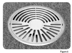
To prevent users from changing the airflow rate from negatively affecting the overall cooling performance and indoor air quality of the system, a throw-adjustable floor swirl diffuser has been developed that allows for personal comfort adjustment (Figure 6). These diffusers create a swirl airflow with strong induction along an inclined axis. Thanks to this swirl effect, the velocity of the supply air rapidly decreases, and its temperature instantly equalizes with the ambient air. The user can adjust the air direction by rotating the diffuser face; thus meeting the Green Star user adjustability criteria.
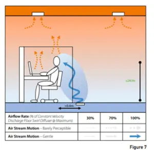
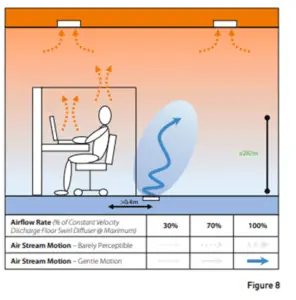
Compared to vertical throw swirl diffusers, throw-adjustable floor diffusers have the following advantages (Figures 7 and 8):
- While it is ideal to place the diffuser 0.4m away from seating, it is possible to place the diffuser immediately next to seats without the risk of drafts, thanks to the ability to redirect the airflow.
- Higher local air movement created by directing the diffuser's airflow towards the user eliminates the sensation of stuffiness for users who prefer increased air movement. If less air movement is desired, the user can turn the diffuser face away from the airflow.
- When air direction adjustment is used for personalized effective temperature setting instead of airflow rate adjustment, throw-adjustable floor diffusers provide the following advantages:
- Since the airflow rate cannot be throttled by the user, indoor air quality is not compromised.
- Since the airflow rate cannot be throttled by the user, thermostatic control is not compromised.
- The throw height remains largely constant; this eliminates the “cold feet, warm head” sensation and stuffiness problem, regardless of user adjustment.
However, throw-adjustable floor swirl diffusers have some limitations:
- When ambient air adjustment is offered to the user via only one of two possible adjustment methods (i.e., air direction), the full spectrum of personalized comfort cannot be maximized.
- Since a vertical discharge option with high induction and rapidly decreasing discharge velocity is not offered, they are not suitable for applications where this type of air pattern is required.
- A motorized VAV damper option is not available for these diffusers, as this would cause fluctuations in throw distance and negatively affect both the vertical temperature gradient in the occupied space and the user's control over air movement adjustment.
Throw-adjustable floor swirl diffusers are ideal for environments with medium to high heat loads where personal comfort adjustment is desired, and they provide this adjustability without disturbing the vertical temperature balance for users. However, these diffusers do not offer a motorized VAV option; because their main advantages – providing effective mixing up to the head level of seated individuals regardless of user adjustment – would be lost in this case.
3.4 Constant Throw Velocity Floor Swirl Diffusers
Constant velocity discharge makes it possible to achieve a largely constant throw distance up to the head level of seated individuals, even when the airflow rate is adjusted. Thus, even when the user sets the diffuser airflow rate to a reduced setting, an excessive vertical temperature gradient does not occur in the occupied space.
The adjustability of airflow rate with this largely constant throw distance, combined with a directed inclined airflow, further enhances the potential for the user to personalize their local thermal environment. This is because increasing or decreasing airflow can be directed towards or away from the user.
The thermal comfort advantage provided by such a wide range of adjustability for the user is particularly important in areas where loads fluctuate strongly, such as perimeter zones, which often require the widest range of user-specific personalization.
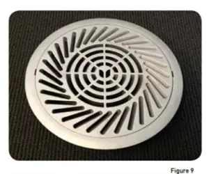
The constant throw velocity floor-type swirl diffuser (Figure 9) allows diffuser components to be mounted in three different configurations thanks to two adjustable dampers (however, only two of these configurations provide largely “constant velocity” throw):
- User-adjustable throw angle, rotation, and airflow rate (throw is largely “constant velocity”).
- Inclined throw with user-adjustable rotation and airflow rate (throw is largely “constant velocity”).
- Vertical throw with user-adjustable airflow rate (throw is variable velocity).
All three configurations above meet the Green Star requirements for user-adjustable credits.
Configuration 1 offers the user the ability to adjust the airflow rate (limited by adjustable stoppers), direction (by rotating the inclined throw pattern), and inclination (provides minimum air movement in the vertical position).
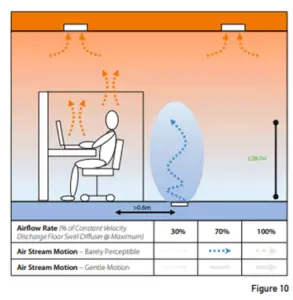
This configuration provides the widest thermal comfort adjustability: Turning the diffuser face counter-clockwise provides a directed inclined airflow with increased airflow rate that can be directed towards the user and creates gentle air movement (Figure 7); turning it clockwise creates a vertical throw with reduced airflow rate, directed away from the user, and in this case, air movement is almost imperceptible (Figure 10). The throw height is largely constant.
This is the most typical configuration for reconfigurable offices, especially in draft-sensitive applications.
Configuration 2 offers the user the ability to adjust the airflow rate (limited by adjustable stoppers) and direction (by rotating the inclined throw pattern).
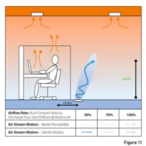
This configuration provides gentle air movement in the space, regardless of the airflow rate setting: Turning the diffuser face counter-clockwise provides an inclined airflow with increased airflow rate that can be directed towards the user (Figure 7); turning it clockwise creates an inclined airflow with reduced airflow rate that can be directed away from the user (Figure 11). The throw height is largely constant.
This is the most typical configuration for offices and workspaces in tropical regions and many parts of Asia-Pacific, where air movement is desired to be felt even at low velocities.
Configuration 3 provides vertical throw and offers the user airflow rate adjustability (limited by adjustable stoppers).
A strong decrease in discharge velocity occurs regardless of the airflow rate setting, and air movement in the space is almost imperceptible (Figures 4 & 5). The throw height varies depending on the airflow rate.
This configuration is generally used in transition areas or zones with very high thermal loads.
Specifically, the constant throw velocity floor swirl diffuser offers the following advantages:
- In Configurations 1 and 2, it is possible to place the diffuser immediately next to seating areas without creating a risk of drafts (although a minimum distance of 0.4m is preferred for optimal air movement control).
- In Configurations 1 and 2, while user airflow rate adjustment is possible, mixing up to the head level of seated occupants is largely maintained. Thus, even though the airflow rate is adjustable, the sensation of stuffiness and the “cold feet, warm head” effect are eliminated.
- In Configurations 1 and 2, turning the diffuser face counter-clockwise increases the flow rate of a gentle, inclined airflow that can be directed towards the user, maximizing the personalized cooling effect.
- In Configuration 1, turning the diffuser face clockwise reduces the airflow rate and produces a high-induction throw in the vertical direction, creating barely perceptible air movement. This provides the lowest level of personalized cooling. In contrast, in Configuration 2, turning clockwise reduces the flow rate of the inclined and rotatable airflow, creating gentle surface-level air movement that can be adjusted by direction.
- Configuration 1 optionally offers electric VAV damper operation. This provides user-personalized air direction and air movement adjustment independently of the automatically adjusted airflow rate.
- Configuration 3 (not a constant velocity configuration) offers high-induction air supply with rapid throw velocity decay; it creates barely perceptible air movement and allows the user to adjust the airflow rate.
The disadvantages of constant throw velocity floor swirl diffusers are:
- Configuration 3 does not offer largely constant velocity throw and therefore does not maintain a constant vertical throw height up to the head level of seated occupants. The throw height varies depending on the user-adjustable airflow rate (Figures 4 and 5). Allowing a wide range of airflow rate adjustment in this configuration can create a sensation of stuffiness and the “cold feet, warm head” effect.
- Due to the option of being assembled in three different configurations, clear defined specifications from the project engineer are required regarding which configuration and damper settings to use.
- The presence of two adjustable dampers potentially leads to a more complex installation process.
Constant throw velocity floor swirl diffusers offer the advantages of three different configurations:
- Maximizing airflow rate, air direction, and air movement adjustability (suitable for most user-reconfigurable office applications),
- Offering airflow rate and direction adjustment while maintaining gentle air movement at head level (generally suitable for offices and workspaces in tropical regions and Asia-Pacific),
- Providing only airflow rate adjustability, with vertically directed and almost imperceptible air movement (suitable for transient areas or applications with very high heat loads) configurations.
Only the last of these three configurations cannot largely maintain mixing up to the head level of seated occupants, independently of user settings. Optional motorized VAV damper operation is available for Configuration 1, providing personalized air direction and air movement adjustability up to the head level of seated occupants within the VAV operating range.
4. CONCLUSIONS
In addition to the floor swirl diffusers presented above, many different designs are available, especially in terms of adjustability. For example, some models allow horizontal to vertical swirl adjustment, while horizontal throw floor swirl diffusers offer the user the ability to adjust the airflow rate. However, this article has focused on the most common floor swirl diffuser designs.
Specifically, horizontal flow floor swirl diffusers have been found suitable for areas with low heat loads, such as libraries.
Vertical flow floor swirl diffusers, on the other hand, are the most suitable solution for transient areas and applications with very high heat loads in commercial offices. These diffusers generally offer the user the option to adjust the airflow rate, but this should only be applied within a limited range and ideally used in areas with low heat loads and minimal thermal fluctuations, such as core zones. Optional motorized VAV adjustment can negatively affect thermal comfort by increasing the vertical temperature gradient as the diffuser throw decreases when the airflow rate is reduced.
Throw-adjustable floor swirl diffusers offer the user the ability to adjust the air direction, thereby largely maintaining the throw up to the head level of seated occupants regardless of the personalized setting. These diffusers are suitable for offices, including areas where user adjustment is needed, especially perimeter zones and areas experiencing high heat load fluctuations. However, these diffusers do not offer motorized VAV modulation, which is often necessary in areas such as meeting rooms.
Constant throw velocity floor swirl diffusers maximize the user's adjustability of the local thermal environment by offering airflow rate, air direction, and air movement adjustment, while largely keeping the throw constant up to the head level of seated occupants (except for the vertical throw configuration). These diffusers adapt to different user air temperature and air movement preferences. They eliminate the risk of “cold feet, warm head” even when motorized VAV control is provided. Optional motorized VAV control also allows the user to personalize air direction and air movement. Constant throw velocity floor swirl diffusers are the most suitable solution for commercial office applications where maximizing user comfort and indoor air quality is the goal.
5. REFERENCES
(a) Books and handbooks: CIBSE Continuing Professional Development: Tutorial – Underfloor Air-Conditioning, 2000
(b) Journal articles and conference papers:
Badenhorst S: “Energy Efficient Air Distribution for Comfort”, IRHACE Journal Vol 8, No 6, 1996 Bauman FS: “Giving Occupants What They Want: Guidelines for Implementing Personal Environmental Control in your Building”, World Workspace Conference, Los Angeles CA, 3–5 Oct 1999
Brown MR: “Underfloor Air Conditioning Systems – Principles and Applications”, Carrier Global Engineering conference, May 2000
Center for Building Performance and Diagnostics: “Flexible and Adaptive HVAC Distribution Systems for Office Buildings”, Air Conditioning and Refrigeration Technology Institute, Walking on Air Energy Presentation, 2001
Daly A: “Underfloor Air Distribution: Lessons Learned”, ASHRAE Journal, May 2002-08-16
Gupta V, Woods JE: “The Performance of Underfloor Air Distribution Systems”, High Performance Buildings Conference, Nashville Tennessee, 2007
Hui SCM, Li Y: “Enhancing Sustainability of Buildings by using Underfloor Air Conditioning Systems”, Symposium on System Design and Operation for Enhancing Sustainability of Buildings, Chongqing, China, 8-10 July 2002
Loudermilk, K J: Underfloor Air Distribution Solutions for Open Office Applications”, ASHRAE Transactions, Vol 105, Part I, 1999
Stanke D: “Underfloor Air Distribution”, Engineers Newsletter, Vol 30, No 4, 2001
Webster T: “Unerfloor Air Distribution: Thermal Stratification”, ASHRAE Journal, May 2002
Woods EW, Novosel D: “Comparative Analysis of Conventional and Underfloor Air Distribution System Performance using the Air Diffusion Performance Index Method”, NEMI, 2008
6. REFERENCES
1. Badenhorst S: “Underfloor Air Distribution”, AIRAH Indoor Air Quality Conference, Canberra, Australia, 2002 2. DIN 1946 Part
2 (January 1994): Heating, Ventilation and Air Conditioning, Requirements relating to Health (VDI Code of practice).
3. Inatomi TA, Abe V, Leite BCC: “Energy Consumption of Underfloor Air Distribution Systems: A Literature Overview”, Conference on Low Energy Architecture, Geneva, Switzerland, 2006
4. Webster T, Lukaschek W, Dickerhoff D, Bauman F: “Energy Performance of Underfloor Air Distribution (UFAD) Systems Part II: Room Air Stratification Full Scale Testing”, Center for the Built Environment, University of California, Berkeley, 2007.
5. Krantz Komponenten: “Air Distribution Systems – Floor Air Outlets”, K 72e/05-1
- Göbel A [Krantz Komponenten]: telephonic interview 25/04/2013
7. Bauman FS: “Task/Ambient Conditioning Systems: Engineering and Application Guidelines”, Center for the Built Environment, University of California Berkeley, World Workplace Conference, Los Angeles CA, Oct 1999
8. Building Owners and Managers Association (BOMA) International and ULI (the Urban Land Institute): “What office tenants want”, BOMA/ULI office tenant survey report, 1999
9. de Dear R, Grager GS: “Developing an adaptive model of thermal comfort and preference” ASHRAE Transactions Vo. 104(1) 1999